Description
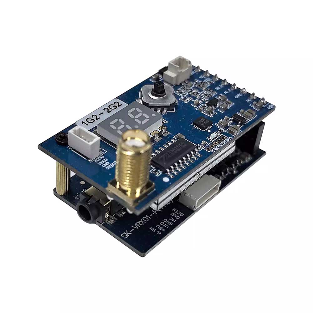
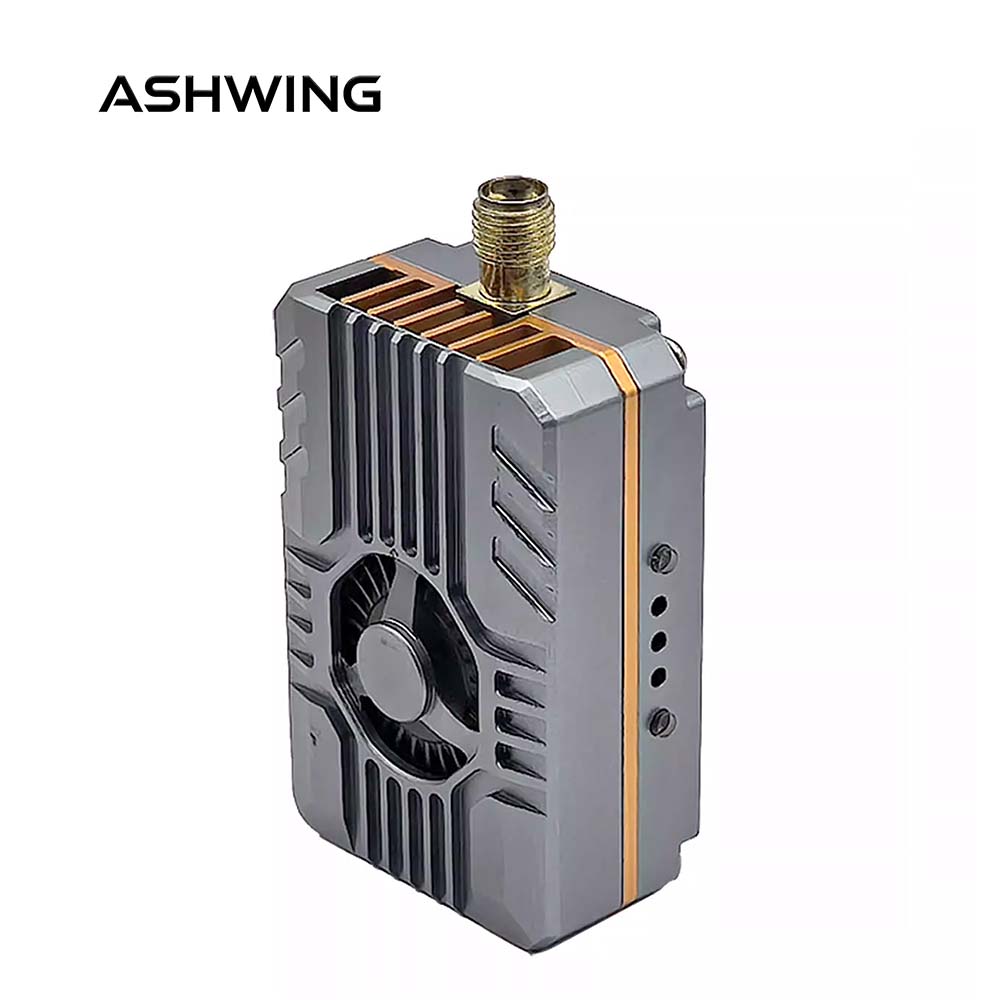
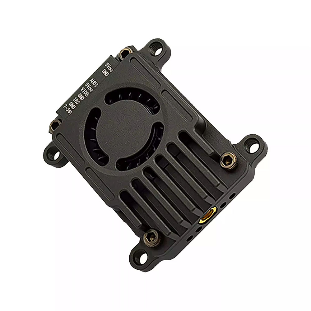
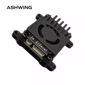
1.2G~1.3G DIP Switch Mode FPV Video Transmitter
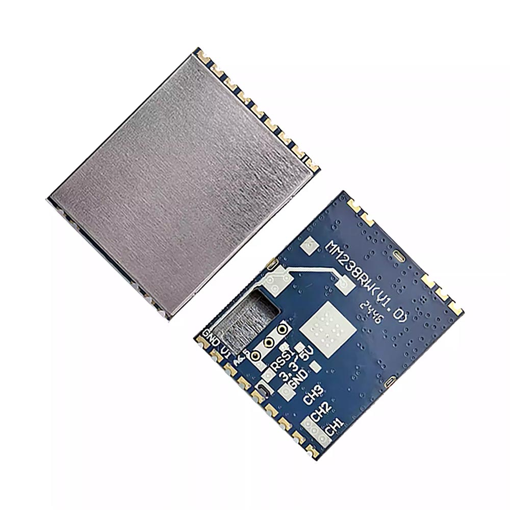
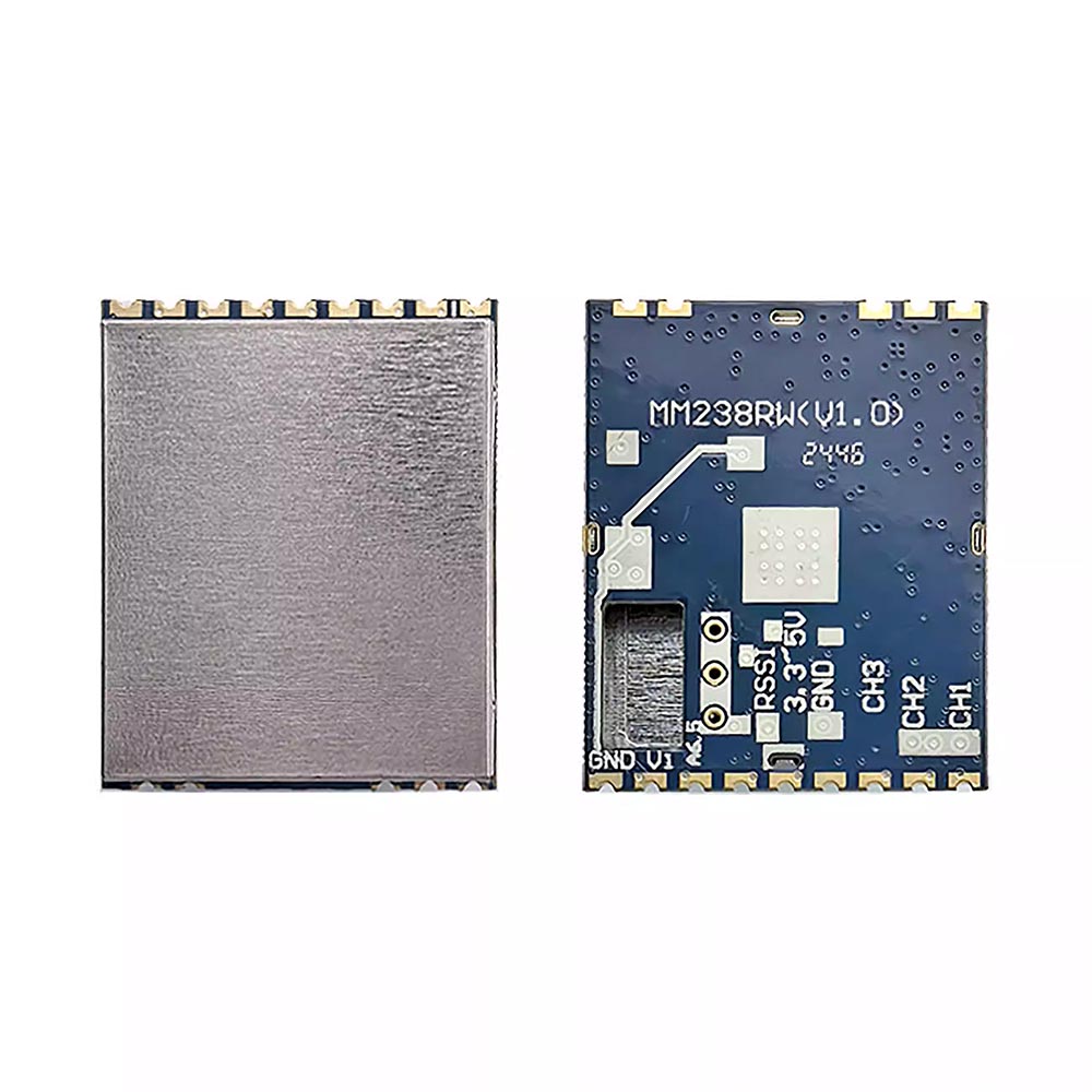
The FPV Video Transmitter VM1373R is a module supporting CVBS signal output, featuring low latency and strong anti-interference capability. It is widely used in FPV drone flying, outdoor entertainment, racing competitions, and professional aerial photography, with frequency controlled by DIP switches.so it is easy to use.
1) General Specifications
| DC Characteristics |
Environmental Specification |
RF |
Video Characteristics |
| Power Supply Voltage |
5.0V |
Operating Temperature |
-10~+65℃ |
Receiving Frequency Range |
1080~1360MHz |
Video Output Impedance |
75Ω, Typ. |
| Current Consumption |
380mA±30mA |
Storing Temperature |
-30~+85℃ |
Input VSWR |
2:1 |
Video Output Level |
1±0.2Vp-p, Typ. |
|
|
Operating Humidity |
85%RH |
Demodulation System |
FM/PLL |
Video Polarity |
Negative |
|
|
|
|
IF Frequency |
480MHz |
|
|
|
|
|
|
Antenna Port Impedance |
50Ω, Typ. |
|
|
|
|
|
|
LO Frequency Stabilization |
±200kHz |
|
|
|
|
|
|
LO Frequency Precision |
±200kHz |
|
|
|
|
|
|
LO Control |
PLL |
|
|
|
|
|
|
Input LO Leakage |
-65dBm |
|
|
|
|
|
|
Receiving Sensitivity |
-95dBm±2 |
|
|
|
|
|
|
Input Level Range |
-95dBm~+5dBm |
|
|
| Video Frequency Response |
±5 dB, Max. 50Hz~6MHz |
| Differential Gain |
±5 %, Max |
| Differential Phase |
±5 Deg., Max |
| 3dB IF Bandwidth |
16.5MHz |
| Signal-to-Noise Ratio S/N |
38dB, Min |
| Dimension |
37mm(L)*26.3mm(W)*4.5mm(H) |
| Weight |
Approx.: 5.5g |
2) Pin Function
| Pin NO. |
Function Description |
| 1 |
DCIN: +5V |
| 2 |
S1: Channel Table (refer to channel table) |
| 3 |
GND |
| 4 |
NC |
| 5 |
NC |
| 6 |
Video Out |
| 7 |
CS3: Channel Table (refer to channel table) |
| 8 |
CS2: Channel Table (refer to channel table) |
| 9 |
CS1: Channel Table (refer to channel table) |
| 10 |
RF Signal Strength Indicator (RSSI) |
| 11 |
GND |
| 12 |
GND |
| 13 |
GND |
| 14 |
1.2G ANT IN |
| 15 |
GND |
3) Channel Table (0 represents low level, 1 represents high level)
| Channel |
Pin7 (CS3) |
Pin8 (CS2) |
Pin9 (CS1) |
Pin2 (S1) |
| CH1: 1080MHz |
0 |
0 |
0 |
1 |
| CH2: 1120MHz |
0 |
0 |
1 |
1 |
| CH3: 1160MHz |
0 |
1 |
0 |
1 |
| CH4: 1200MHz |
0 |
1 |
1 |
1 |
| CH5: 1240MHz |
1 |
0 |
0 |
1 |
| CH6: 1280MHz |
1 |
0 |
1 |
1 |
| CH7: 1320MHz |
1 |
1 |
0 |
1 |
| CH8: 1360MHz |
1 |
1 |
1 |
1 |
| CH9: 1258MHz |
1 |
0 |
0 |
0 |
4) RSSI Output Voltage Reference Values
Using an E4421B signal generator as the signal input source for the module, RSSI output voltage at the 1080MHz frequency point, for reference only.
| Input Signal Strength |
RSSI Output Voltage |
Input Signal Strength |
RSSI Output Voltage |
| -90dBm |
0.38V |
-60dBm |
1.035V |
| -85dBm |
0.48V |
-55dBm |
1.15V |
| -80dBm |
0.58V |
-50dBm |
1.24V |
| -75dBm |
0.68V |
-45dBm |
1.26V |
| -70dBm |
0.81V |
-40dBm |
1.28V |
| -65dBm |
0.92V |
-30dBm |
1.46V |


Reviews
There are no reviews yet.