Analog fpv Video Receiver SK-VRX01 1.2G/1.3G/1.7G/2.2G 80CH Receiver FPV Drones
$56.99
- 1.1G 2.3G 80CH(1100MHz ~ 2360MHz)
- Input Voltage:7V~28V (2~7S)
- Receiver sensitivity:-95dBm±3dBm
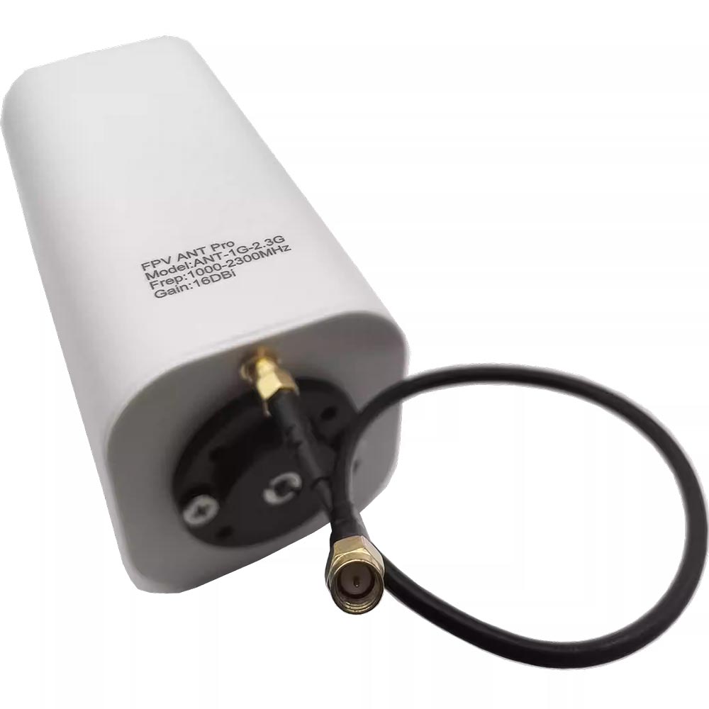
- Antenna Interface:SMA
Description
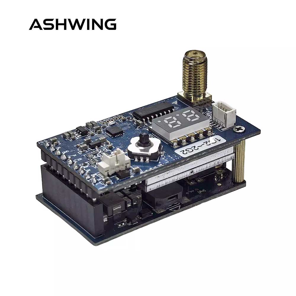
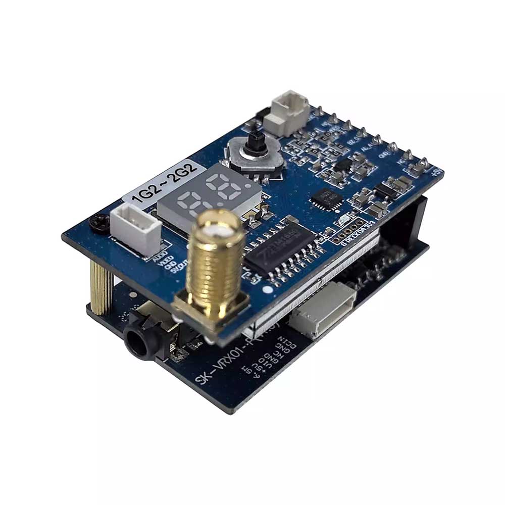
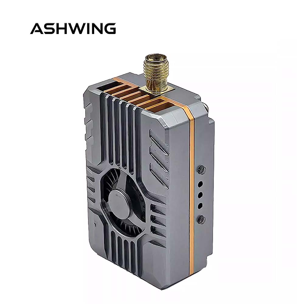
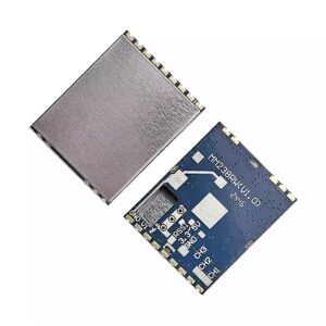
SK-VRX01 fpv Video Receiver / Alert Receiver
SK-VRX01 is a 1.1G~2.3G analog FPV video receiver and alert receiver. It outputs CVBS signal and is compatible with various display terminals (compatible with Fatshark goggles, SKYZONE goggles, DJI goggles V1/V2, analog monitors, and can simultaneously output video signal for external DVR). It supports auto-scanning and IRC protocol frequency selection, built-in buzzer alarm and video signal monitoring (can monitor and alert signals within the receiver’s frequency range in the surrounding environment). Featuring low latency and strong anti-interference capability, it is widely used in FPV drone flying, outdoor entertainment, racing competitions, professional aerial photography and other fields.
- 1.1G 2.3G 80CH(1100MHz ~ 2360MHz)
- Input Voltage:7V~28V (2~7S)
- Receiver sensitivity:-95dBm±3dBm
- Antenna Interface:SMA
I.fpv Video Receiver General Characteristics
| Item | SPEC. |
|---|---|
| Input Voltage | DC 7V~28V (2~7S) |
| Current Consumption | 250±20mA @DC 12V |
| Output Voltage | 5V±0.5V output (MAX 500mA when input voltage > 7.2V) |
| Channel customer | 80CH (1100MHz ~ 2360MHz) |
| Receiving Sensitivity | -95dBm±3dBm |
| Modulation type | FM |
| Frequency control | PLL |
| Frequency Stability | ±100KHz (Typ.) |
| Frequency precision | ±200KHz (Typ.) |
| S/N (Fo ± 3) | >70dBc |
| Antenna Port Impedance | 50 Ohms |
| Antenna Connector | SMA (female pin, inner hole) |
| Video System | PAL / NTSC |
| Video output level range | 1V±0.2Vp-p typ. |
| Video Signal Format | CVBS |
| Operating Temperature | -10℃~+60℃ |
| Profile dimension | 48mm * 27mm * 20mm (excluding SMA connector) |
| Weight | 20.5g (with base plate, without antenna) |
II.
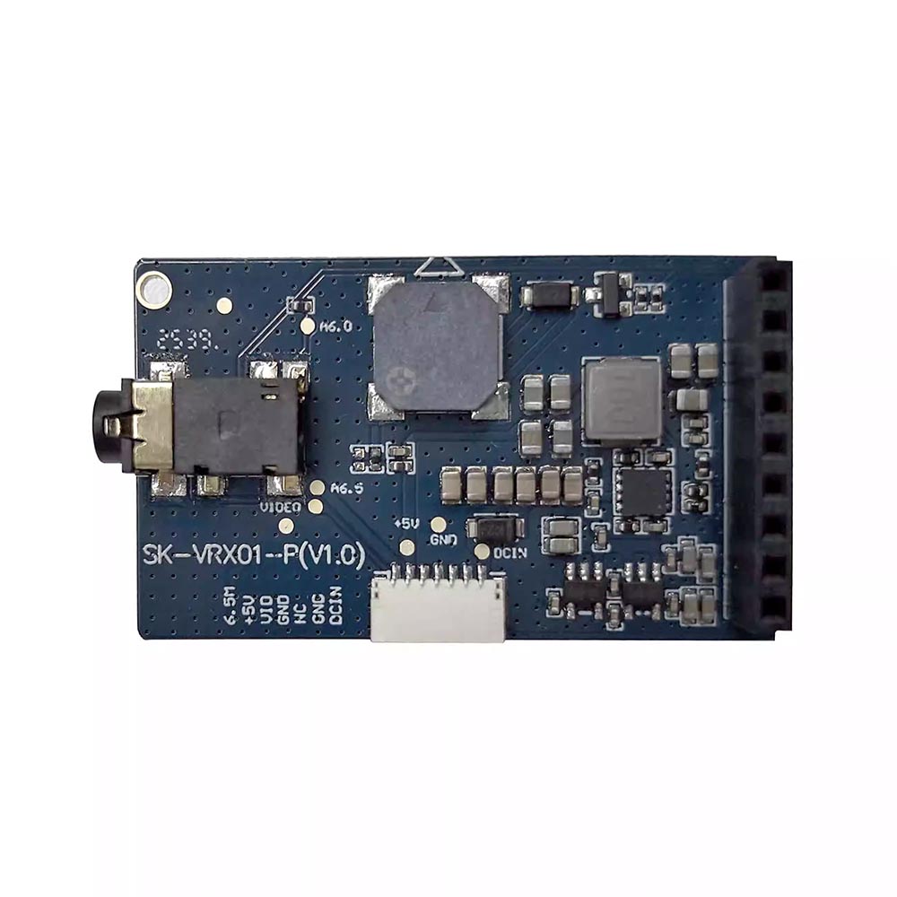
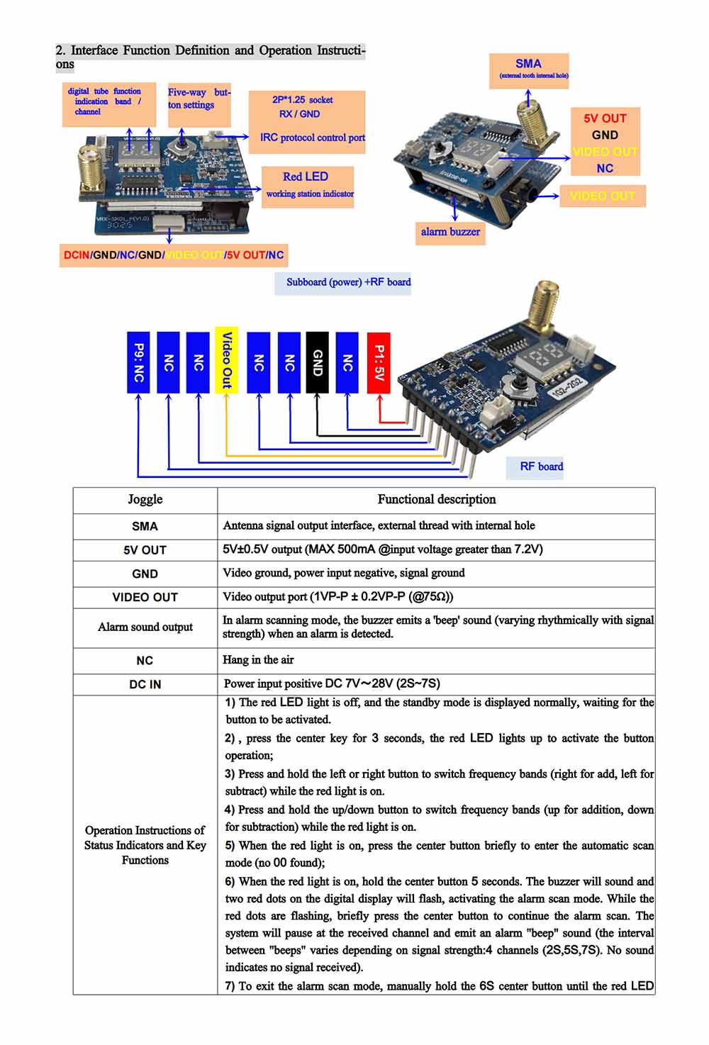
fpv Video Receiver Interface Function Definition and Operation Instructions
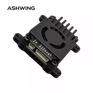
| Interface | Function Description |
|---|---|
| SMA | Antenna signal output interface, external thread inner hole |
| 5V OUT | 5V±0.5V output (MAX 500mA @ input voltage > 7.2V) |
| GND | Video ground, power input negative, signal ground |
| VIDEO OUT | Video output port (1VP-P ± 0.2VP-P(@75Ω)) |
| Alert audio output | In alarm scanning mode, when alert information is received, the buzzer emits “di di” sound (rhythm varies with signal strength) |
| NC | Not connected |
| DC IN | Power input positive DC 7V~28V (2S~7S) |
fpv Video Receiver Status LED and Button Function Operation Instructions
- Red LED off: normal standby mode waiting for key press; buttons are inactive.
- Press and hold center button for 3 seconds: red LED lights up, activates button operation.
- When red LED is on: short press left or right button to switch frequency group (right +, left -).
- When red LED is on: short press up or down button to switch frequency group (up +, down -).
- When red LED is on: short press center button to enter auto-scan mode (if no channel found, displays “00”).
- When red LED is on: press and hold center button for 5 seconds, buzzer sounds and both red dots on the digital tube flash; enters alarm scan mode. While red dots are flashing, short press center button to continue alarm scanning. When an alert is received in alarm mode, it stops on the received channel and emits a “di di” alarm sound (different intervals according to signal strength: 4 levels – 2S, 5S, 7S, no sound = no signal).
- To exit alarm scan mode: manually press and hold center button for 6 seconds until red LED turns off. For other function modes, if no button operation within 10 seconds, it will automatically exit and the red LED turns off.
(Remark: In alert mode, if power is cut off and then reapplied, it displays frequency group/frequency; to enter alert mode again, you need to restart it.)
fpv Video Receiver Frequency Points and Digital Tube Display Status:
| Channel | CH1 | CH2 | CH3 | CH4 | CH5 | CH6 | CH7 | CH8 |
|---|---|---|---|---|---|---|---|---|
| Freq (MHz) | 2220 | 2240 | 2260 | 2280 | 2300 | 2320 | 2340 | 2360 |
| Display | 11 | 12 | 13 | 14 | 15 | 16 | 17 | 18 |
| Freq (MHz) | 2060 | 2080 | 2100 | 2120 | 2140 | 2160 | 2180 | 2200 |
| Display | 21 | 22 | 23 | 24 | 25 | 26 | 27 | 28 |
| Freq (MHz) | 1920 | 1960 | 2000 | 2040 | 2080 | 2120 | 2160 | 2200 |
| Display | 31 | 32 | 33 | 34 | 35 | 36 | 37 | 38 |
| Freq (MHz) | 1900 | 1940 | 1980 | 2020 | 2060 | 2100 | 2140 | 2180 |
| Display | 41 | 42 | 43 | 44 | 45 | 46 | 47 | 48 |
| Freq (MHz) | 1740 | 1760 | 1780 | 1800 | 1820 | 1840 | 1860 | 1880 |
| Display | 51 | 52 | 53 | 54 | 55 | 56 | 57 | 58 |
| Freq (MHz) | 1720 | 1740 | 1760 | 1780 | 1800 | 1820 | 1840 | 1860 |
| Display | 61 | 62 | 63 | 64 | 65 | 66 | 67 | 68 |
| Freq (MHz) | 1420 | 1460 | 1500 | 1540 | 1580 | 1620 | 1660 | 1700 |
| Display | 71 | 72 | 73 | 74 | 75 | 76 | 77 | 78 |
| Freq (MHz) | 1400 | 1440 | 1480 | 1520 | 1560 | 1600 | 1640 | 1680 |
| Display | 81 | 82 | 83 | 84 | 85 | 86 | 87 | 88 |
| Freq (MHz) | 1100 | 1140 | 1800 | 1220 | 1260 | 1300 | 1340 | 1380 |
| Display | 91 | 92 | 93 | 94 | 95 | 96 | 97 | 98 |
| Freq (MHz) | 1080 | 1120 | 1160 | 1200 | 1240 | 1280 | 1320 | 1360 |
| Display | A1 | A2 | A3 | A4 | A5 | A6 | A7 | A8 |
III.fpv Video Receiver Application Brief
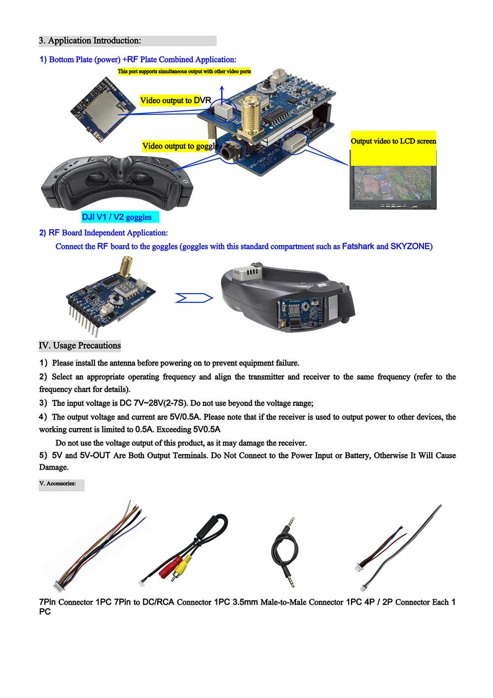
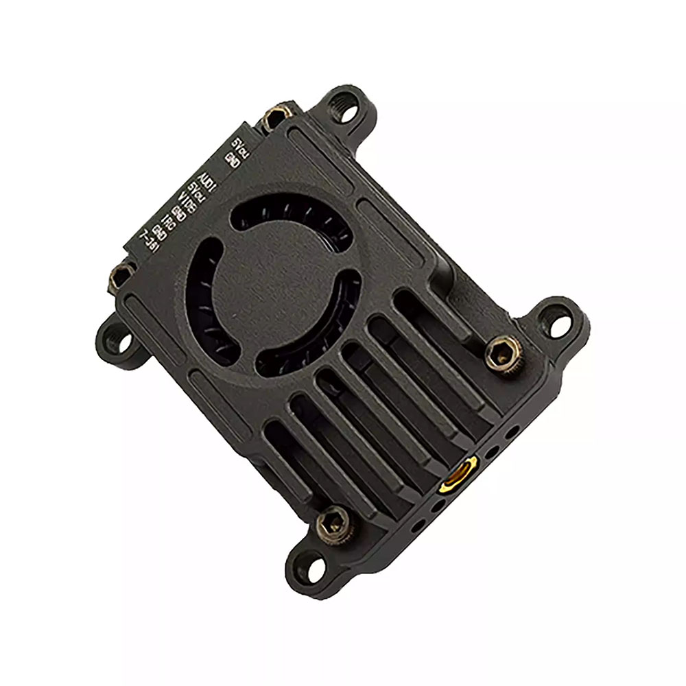
1) Base plate (power) + RF board combined application:
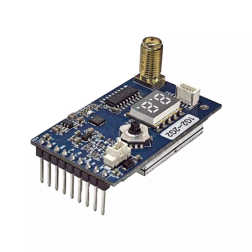
2) RF board standalone application:
Insert the RF board into goggles (Fatshark, SKYZONE or other goggles with this standard bay).
IV.fpv Video Receiver Precautions for Use
- Always connect the antenna before powering on to avoid equipment malfunction.
- Select the appropriate operating frequency and set both transmitter and receiver to the same frequency (refer to frequency table).
- Input voltage range: DC 7V~28V (2-7S). Do not use outside this range.
- Output voltage/current: 5V/0.5A. If you need to power other devices via the receiver’s output, the current must be within 0.5A. Do not use the product’s voltage output terminal for loads exceeding 5V/0.5A, otherwise the receiver may be damaged.
- Both 5V and 5V-OUT are output terminals. Do not connect them to a power input or battery, otherwise damage will occur.
V.fpv Video Receiver Accessories
(No detailed list provided in original document)
Additional information
| Weight | 0.1 kg |
|---|---|
| Dimensions | 5 × 5 × 5 cm |
Related products
-


Analog FPV Video Transmitter MM238RW 5.8G 4.9G 6.0G Receiver VRX FPV Drones
$59.99 Add to basket -
Analog fpv Video Transmitter SK-VTX07 2.2G 2G 4.5W VTX 16CH Receiver VTX FPV Drones
$85.99 Add to basket -
FPV Drone Parts Analog Video Transmitter 4.9G 5.8G 6G 72CH 1.6W Receiver High-power long range
$52.99 Add to basket -
Analog FPV Video Transmitter 1.2G~1.3G 9CH Video Receiver VRX VM1373R for FPV Drones
$66.99 Add to basket


Reviews
There are no reviews yet.