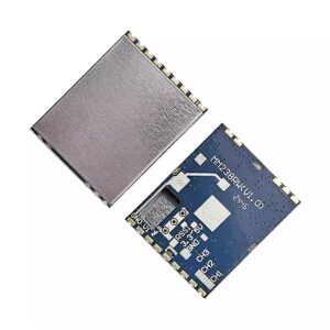
Analog FPV Video Transmitter 3.3G 4.5W 64CH Receiver VTX-F10 VRX FPV Drones
$75.99
- 2.0G~2.2G 8CH 4.5W (2000MHz ~ 2200MHz)
- Power supply: DC 7V-36V Output voltage: DC 5V
- Power: PIT Mode, 25mW, 800mW, 4500mW
- Control protocol: IRC, supports OSD parameter adjust
Description
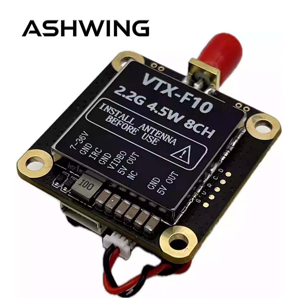
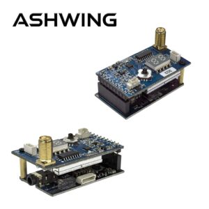
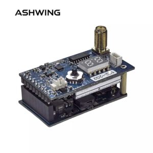
VTX-F10 FPV Video Transmitter
FPV Video Transmitter 2.0G·2.2G · 8CH · 4.5W · IRC · V1.0
The FPV Video Transmitter VTX-F10 is a video transmitter with an output power of over 4.5W. It features a compact size,lightweight design, low power consumption, low latency, and strong anti-interference capability. FPV Video Transmitter ,It is equipped with a built-in aluminum heat sink and cooling fan for active heat dissipation, ensuring stablehigh-power transmission. The transmitter includes an automatic temperature protection function toprevent overheating during prolonged ground configuration. It supports IRC protocol and OSDconfiguration, and is widely used in FPV drone flights, outdoor entertainment, racing competitions, andprofessional aerial photography.
II. FPV Video Transmitter Interface Function Definition and Operation Instruction
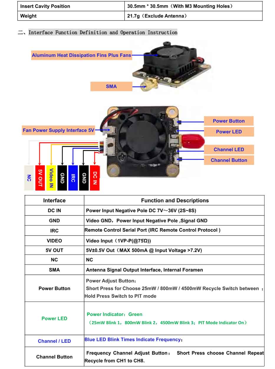
DC IN, GND, IRC, VIDEO, 5V OUT, SMA, Power button, LEDs
| Interface | Function and Descriptions |
|---|---|
| DC IN | Power Input Negative Pole DC 7V~36V (2S~8S) |
| GND | Video GND, Power Input Negative Pole, Signal GND |
| IRC | Remote Control Serial Port (IRC Remote Control Protocol) |
| VIDEO | Video Input (1VP-P(@75Ω)) |
| 5V OUT | 5V±0.5V Out (MAX 500mA @ Input Voltage >7.2V) |
| NC | NC |
| SMA | Antenna Signal Output Interface, Internal Foramen |
| Power Button | Power Adjust Button: Short Press to choose 25mW / 800mW / 4500mW (recycle switch); Hold Press to switch to PIT mode. |
| Power LED | Power Indicator: Green (25mW: Blink 1, 800mW: Blink 2, 4500mW: Blink 3; PIT Mode: solid ON) |
| Channel / LED | Blue LED Blink Times Indicate Frequency; |
| Channel Button | Frequency Channel Adjust Button: Short press to choose channel, repeat recycle from CH1 to CH8. |
FPV Video Transmitter Power Levels & Channel Configuration
Power Settings – Green LED Indication
| Green LED Recycle Blink | On | Blink 1 | Blink 2 | Blink 3 |
|---|---|---|---|---|
| Power (mW) | PIT | 25mW | 800mW | 4500mW |
This FPV video transmitter is equipped with a temperature protection feature. When the temperature exceeds 100°C, the transmitter will automatically reduce its output power by one level. If the temperature remains above 100°C, it will continue to decrease the power level step by step until it reaches the minimum output level (25mW). Once the temperature drops to 95°C, the transmitter will restore the output power to the originally set level.
Frequency Channel & Blue LED Status
| Channel | CH1 | CH2 | CH3 | CH4 | CH5 | CH6 | CH7 | CH8 |
|---|---|---|---|---|---|---|---|---|
| LED Status | Blink 1 | Blink 2 | Blink 3 | Blink 4 | Blink 5 | Blink 6 | Blink 7 | Blink 8 |
| Frequency (MHz) | 2000 | 2040 | 2080 | 2120 | 2160 | 2200 | 2240 | 2280 |
* CH5 frequency corrected from original “21600 MHz” to 2160 MHz per context.
Remote Control OSD Parameter Tuning (IRC Tramp)
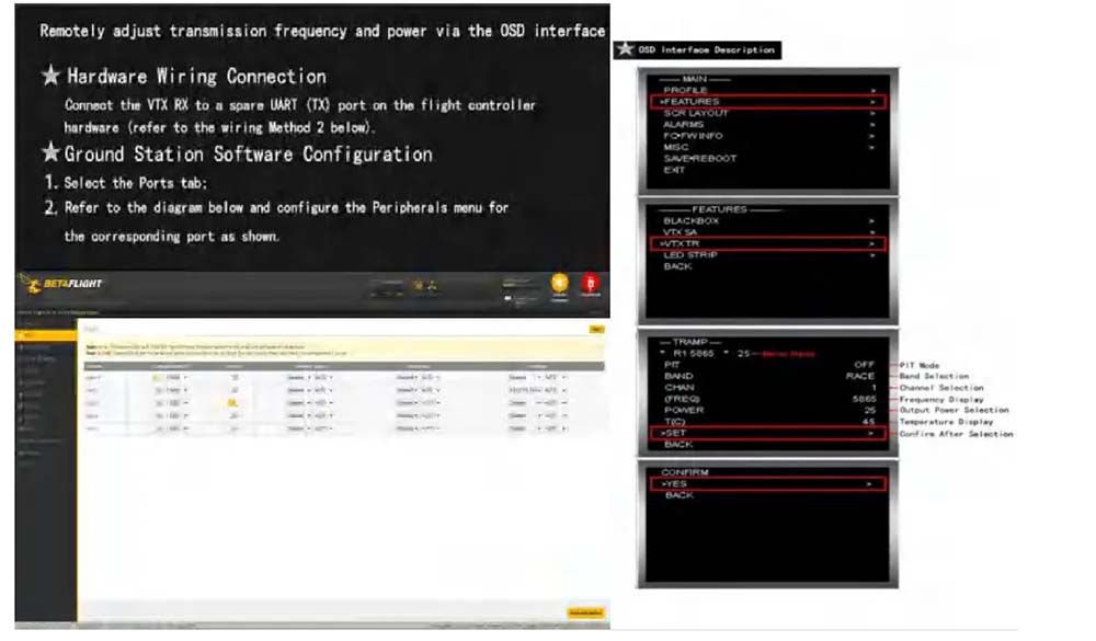
They respectively correspond to the transmission power of this machine: 25mW, 800mW, 4500mW.
• IRC protocol support • OSD adjustable via serial port (IRC Tramp).
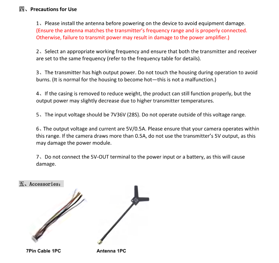
⚠️ Important Precautions & Safe Usage
- 1 Always install the antenna before powering on — to avoid equipment damage. Ensure the antenna matches the transmitter’s frequency range and is properly connected. Otherwise, failure to transmit power may result in damage to the power amplifier.
- 2 Select an appropriate working frequency and ensure that both the transmitter and receiver are set to the same frequency (refer to the frequency table for details).
- 3 The transmitter has high output power. Do not touch the housing during operation to avoid burns. (It is normal for the housing to become hot — this is not a malfunction.)
- 4 If the casing is removed to reduce weight, the product can still function properly, but the output power may slightly decrease due to higher transmitter temperatures.
- 5 The input voltage should be 7V–36V (2S–8S). Do not operate outside of this voltage range.
- 6 The output voltage and current are 5V / 0.5A. Please ensure that your camera operates within this range. If the camera draws more than 0.5A, do not use the transmitter’s 5V output, as this may damage the power module.
- 7 Do not connect the 5V-OUT terminal to the power input or a battery, as this will cause damage.
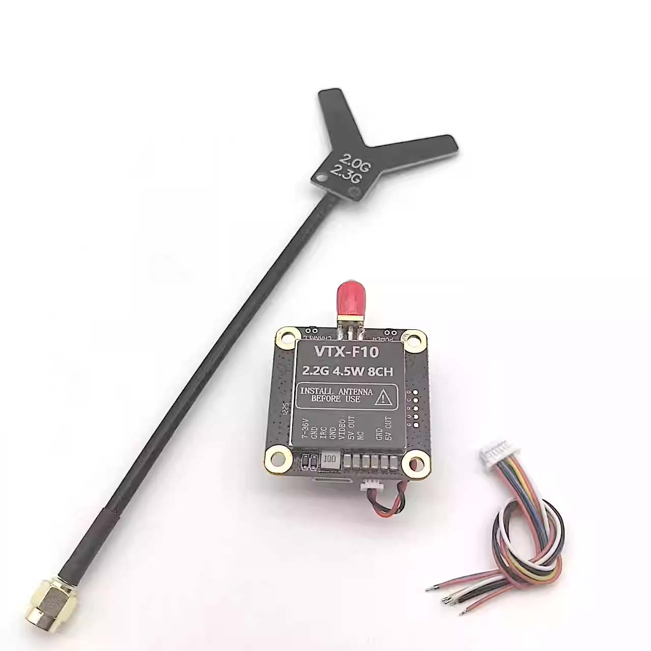
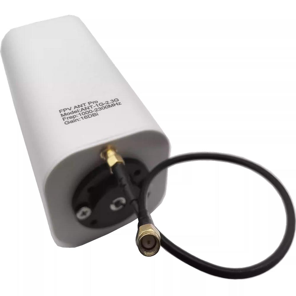
FPV Video Transmitter Accessories Included
| 7Pin Cable | 1 PC |
| Antenna | 1 PC |
* Compatible 2.0G~2.3G antenna, 7-pin harness for connection.
Editor’s note: CH5 frequency in original document listed as “21600 MHz” – corrected to 2160 MHz based on context and 2GHz band plan.
Additional information
| Weight | 0.1 kg |
|---|---|
| Dimensions | 5 × 5 × 5 cm |
Related products
-


Analog fpv Receiver SK-VRX02 3.0G/3.3G/3.8G 80CH Video Receiver VRX FPV Drones
$61.99 Add to basket -
Analog fpv Video Receiver SK-VRX01 1.2G/1.3G/1.7G/2.2G 80CH Receiver FPV Drones
$56.99 Add to basket -
Analog FPV Video Transmitter MM238RW 5.8G 4.9G 6.0G Receiver VRX FPV Drones
$59.99 Add to basket -
Analog FPV Video Transmitter 1.2G~1.3G 9CH Video Receiver VRX VM1373R for FPV Drones
$66.99 Add to basket


Reviews
There are no reviews yet.