")
")
")
")
The fpv Video Transmitter VTX-F11 is a video transmitter with an output power of over 5.5W. It features a compact
size, lightweight design, low power consumption, low latency, and strong anti-interference capability.
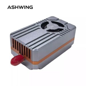
and It is equipped with a built-in aluminum heat sink and cooling fan for active heat dissipation, ensuring
stable high-power transmission. The transmitter includes an automatic temperature protection
function to prevent overheating during prolonged ground configuration. It supports IRC protocol and
OSD configuration, and is widely used in FPV drone flights, outdoor entertainment, racing competitions,
and professional aerial photography.
- 1.9G 9CH 5.5W (1080MHz ~ 1360MHz)
- Power supply: 7V-36V
- Output voltage: 5V
- Powe:PIT Mode, 25mW, 800mW, 5500mW
- Control protocol: IRC, supports OSD parameter adjust
- Antenna Interface:SMA
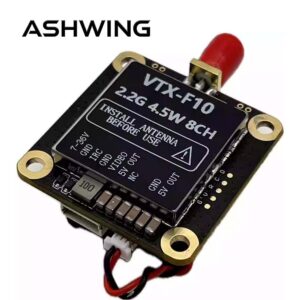
VTX-F11 fpv Video Transmitter
I. General Characteristics
| Item | SPEC. |
|---|---|
| Input Voltage | DC 7V~36V (2~8S) |
| Output Voltage | 5V±0.5V Output (MAX 500mA, Input Voltage >7.2V) |
| Channel Number | 9CH (1080MHz ~ 1360MHz – freely writable within this range, but only one frequency can be written at a time) |
| Transmitter Power | PIT Mode, 25mW, 800mW, 5500mW |
| Control Protocol | IRC Tramp, support OSD adjust parameter |
| Modulation type | FM |
| Frequency control | PLL |
| Frequency Stability | ±100KHz (Typ.) |
| Frequency precision | ±200KHz (Typ.) |
| S/N (Fo ± 3) | >70dBc |
| Antenna Impedance | 50 Ohms |
| Antenna Interface | SMA |
| Video Format | PAL / NTSC |
| Video Output Level Range | 1V±0.2Vp-p type |
| Video Signal Format | CVBS |
| Operating Temperature | -10℃~+60℃ |
🔹 Built‑in fan + aluminum heatsink
🔹 IRC Tramp / OSD
🔹 Auto temperature protection
II. Analog fpv Video Transmitter Interface Function Definition & Operation Instruction

| Interface | Function and Descriptions |
|---|---|
| DC IN | Power input negative pole DC 7V~36V (2S~8S) |
| GND | Video GND, power input negative, signal ground |
| IRC | Remote control serial port (IRC remote control protocol) |
| VIDEO | Video input (1VP-P(@75Ω)) |
| 5V OUT | 5V±0.5V output (MAX 500mA @ input voltage >7.2V) |
| NC | NC |
| SMA | Antenna signal output interface, internal foramen |
| Power Button | Power adjust button: Short press → cycle 25mW / 800mW / 5500mW; Hold press → switch to PIT mode |
| Power LED | Power indicator: Green (25mW: blink 1, 800mW: blink 2, 5500mW: blink 3; PIT Mode: solid ON) |
| Channel / Band LED | Blue LED blink numbers indicate frequency |
| Channel Button | Frequency channel adjust button: Short press → cycle CH1 to CH8 repeatedly (CH9 accessible via specific frequency) |
Power Level & Green LED Indication
| Green LED Status | On (solid) | Blink 1 | Blink 2 | Blink 3 |
|---|---|---|---|---|
| Power (mW) | PIT mode | 25mW | 800mW | 5500mW |
This fpv video transmitter is equipped with a temperature protection feature. When the temperature exceeds 100°C, the transmitter will automatically reduce its output power by one level. If the temperature remains above 100°C, it will continue to decrease the power level step by step until it reaches the minimum output level (25mW). Once the temperature drops to 95°C, the transmitter will restore the output power to the originally set level.
Frequency Channels & LED Indicator (Blue LED Blink)
| Channel | CH1 | CH2 | CH3 | CH4 | CH5 | CH6 | CH7 | CH8 | CH9 |
|---|---|---|---|---|---|---|---|---|---|
| LED Status (Blink count) |
Blink 1 | Blink 2 | Blink 3 | Blink 4 | Blink 5 | Blink 6 | Blink 7 | Blink 8 | Blink 9 |
| Frequency (MHz) | 1080 | 1120 | 1160 | 1200 | 1240 | 1280 | 1320 | 1360 | 1258 |
Flight control OSD – video transmitter power settings: 25, 800, 5500
These correspond to the transmission power levels: 25mW, 800mW, 5500mW.
• IRC protocol supported • OSD adjustable via serial port (IRC Tramp).
fpv Video Transmitter Important Precautions & Safe Usage

- Always install the antenna before powering on — avoid equipment damage. Ensure the antenna matches the transmitter’s frequency range and is properly connected. Otherwise, failure to transmit power may result in damage to the power amplifier.
- Select an appropriate working frequency and ensure both transmitter and receiver are set to the same frequency (refer to frequency table).
- High output power – risk of burns. Do not touch the housing during operation; it is normal for the housing to become hot – this is not a malfunction.
- If the casing is removed to reduce weight, the product still functions properly, but output power may slightly decrease due to higher transmitter temperature.
- Input voltage range: DC 7V–36V (2S–8S). Do not operate outside this range.
- Output voltage/current: 5V / 0.5A. Verify your camera operates within this limit. If the camera draws more than 0.5A, do not use the transmitter’s 5V output – may damage the power module.
- Never connect the 5V-OUT terminal to power input or battery — will cause permanent damage.
The VTX-F11 allows you to freely write one frequency within 1080MHz–1360MHz (but only one custom frequency at a time). Refer to the 9 pre‑set channels for quick selection.


Reviews
There are no reviews yet.